My contact person
Select location

After selection of your ZIP code, we designate the relevant staff to attend to you at once.

INT(EN)

drylin® T - System design, horizontal, 1 rail and 1 carriage

2nd Step:

Check whether the clearances of the aggressive forces lie within the permitted values (see Maximum permitted clearances).

Maximum permitted clearances:

Option: 1 rail, 1 carriage
sy + sz < 2 Lx - Y0
ay + az < 2 Lx - Y0
sy < 5 Zm
sz < 5 Zm

3rd Step:

Calculate the required driving power

3.1

Center of mass in x- and z-direction within the carriage(s)

3.2

Center of mass in z-direction outside the carriage(s)

3.3

Center of mass in x-direction outside the carriage(s)
In case the position of the center of mass cannot be classified:


4th Step:

Calculate the maximum bearing load

4.1

Maximum bearing load in y-direction

4.2

Maximum bearing load in z-direction
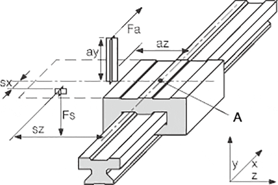
A = Point of origin


Variables in the calculation:

Fa: Driving power [N]
Fs: Mass force [N]
Fy, Fz: Bearing load in y- or z-direction [N]
sx, sy, sz: Clearance of the mass force
in x-, y- or z-direction
[mm]
ay, az: Clearance of the driving power
in y- or z-direction
[mm]
wx: Clearance of the carriage on a rail [mm]
LX: Constant based on the installation size [mm]
Zm: Constant based on the installation size [mm]
Y0: Constant based on the installation size [mm]
b: Clearance of the guide rails [mm]
µ: Coefficient of friction,
µ = 0 in static loads,
µ = 0.2 in dynamic loads
 
ZW: Number of carriages per rail  


The constant values:

Order no. LX ZM Y0
  [mm] [mm] [mm]
TW-01-15 29 16 11,5
TW-01-20 35 23 15,0
TW-01-25 41 25 19,0
TW-01-30 49 29 21,5


Coefficients:

  1 rail,
1 carriages
K1 |(ay+Y0)/Lx|
K2 (sy+Y0)/Lx
K3 |az/Lx|
K4 |sx/Lx|
K5 sz/Lx
K6 |(sy+Y0)/Zm|
K7 |sz/Zm|

5th Step:

Check the maximum bearing load of the most strongly stressed bearing with the calculated load in Step No. 4.

Maximum permitted load:

Order no. Fymax, Fzmax
[N]
TW-01-15 2000
TW-01-20 3700
TW-01-25 5000
TW-01-30 7000

6th Step:

Determination of the maximum permitted speed for the load in Step No. 4
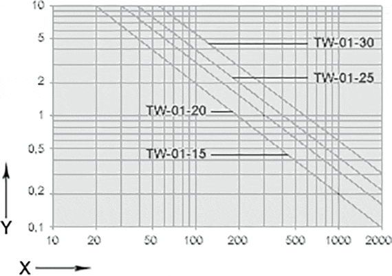
Diagram for the determination of the maximum permitted speed for the determined bearing load.
X = centric bearing load [N]
Y = permitted mean velocity [m/s]


The terms "Apiro", "AutoChain", "CFRIP", "chainflex", "chainge", "chains for cranes", "ConProtect", "cradle-chain", "CTD", "drygear", "drylin", "dryspin", "dry-tech", "dryway", "easy chain", "e-chain", "e-chain systems", "e-ketten", "e-kettensysteme", "e-loop", "energy chain", "energy chain systems", "enjoyneering", "e-skin", "e-spool", "fixflex", "flizz", "i.Cee", "ibow", "igear", "iglidur", "igubal", "igumid", "igus", "igus improves what moves", "igus:bike", "igusGO", "igutex", "iguverse", "iguversum", "kineKIT", "kopla", "manus", "motion plastics", "motion polymers", "motionary", "plastics for longer life", "print2mold", "Rawbot", "RBTX", "readycable", "readychain", "ReBeL", "ReCyycle", "reguse", "robolink", "Rohbot", "savfe", "speedigus", "superwise", "take the dryway", "tribofilament", "triflex", "twisterchain", "when it moves, igus improves", "xirodur", "xiros" and "yes" are legally protected trademarks of the igus® GmbH/ Cologne in the Federal Republic of Germany and where applicable in some foreign countries. This is a non-exhaustive list of trademarks (e.g. pending trademark applications or registered trademarks) of igus GmbH or affiliated companies of igus in Germany, the European Union, the USA and/or other countries or jurisdictions.

igus® GmbH points out that it does not sell any products of the companies Allen Bradley, B&R, Baumüller, Beckhoff, Lahr, Control Techniques, Danaher Motion, ELAU, FAGOR, FANUC, Festo, Heidenhain, Jetter, Lenze, LinMot, LTi DRiVES, Mitsubishi, NUM,Parker, Bosch Rexroth, SEW, Siemens, Stöber and all other drive manufacturers mention on this website. The products offered by igus® are those of igus® GmbH